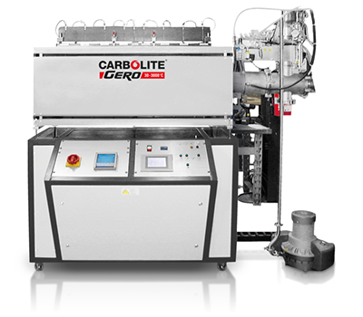
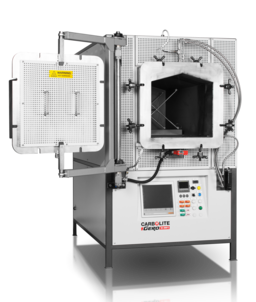
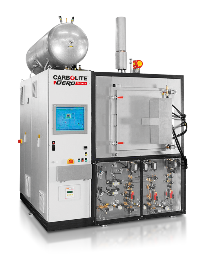
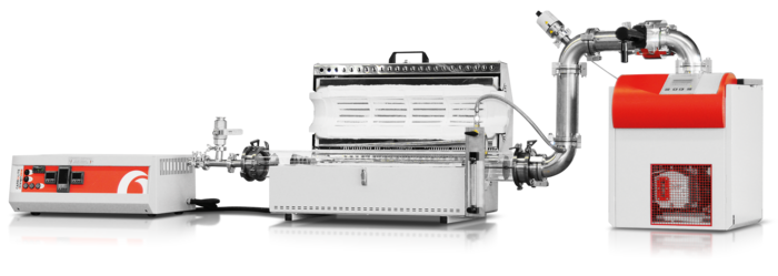
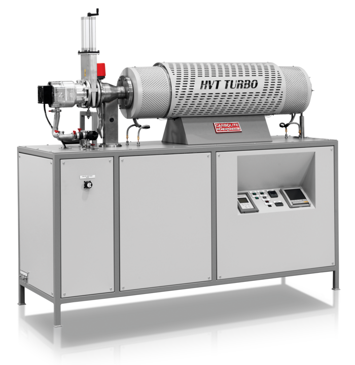
Most common for special atmospheres and ultra high vacuum are the following options (details below):
- Fully controlled inert gas atmosphere in vacuum chamber furnaces
- Reactive gases (H2, CO, CO2, H2S, H2O, CH4 & C2H4 and others on request) option
- Vacuum pump options
- Partial pressure option
- Afterburner (thermal, catalytic or with active propane gas flame) option
- Modified atmosphere with metallic retorts in standard chamber furnaces
- SiC tiles for element protection in standard chamber furnaces
1. Fully controlled inert gas atmosphere in vacuum chamber furnaces
The standard GLO, LHT, HTK, HBO, HTBL and V-L vacuum chamber furnaces are fitted with a full inert gas control system as standard. Depending on the size and maximum temperature, semi-automated controls with flowmeters or fully automated controls via a PLC with touch screen and mass flowmeters are available.
Special Atomosphere and Ultra High Vacuum |
All vacuum chamber furnaces are fitted with one inert gas control as a standard. Additional gas controls are available as an option.
All vacuum chamber furnaces are available with the full range of optional vacuum pumps such as rotary vane pumps, roots pumps, diffusion pumps and turbo pumps. In some cases a vacuum pump is mandatory for safe use of the furnace.
2. Reactive gases (H2, CO, CO2, H2S, H2O, CH4 & C2H4 and others on request) option
All vacuum chamber furnaces can be modified to work safely with H2, CO, CO2, H2S, H2O, CH4 or C2H4.
In principle, a vacuum chamber furnace for use with reactive gases is fully automated and fitted with the following:
- Controlled by SIEMENS S7-300 with either panel TP1900 or WinCC
- Installation for an inert gas e.g. nitrogen or argon controlled by MFC (mass flow controller)
- Installation for a reactive gas controlled by MFC (mass flow controller)
Reactive gas sensor - Active afterburner for safe combustion
- Safety purge tank
- SIL 2 standard for safety related parts
For safety reasons, the gas supply of a furnace using inert and reactive gases is designed in accordance with EN 746-3. This Standard stipulates that the furnace must be free of atmospheric oxygen before it is heated up and before the introduction of combustible gases. In addition, all safety statuses are monitored. In dangerous situations, measures must be initiated e.g. purging of the furnace with the inert gas stored in the safety purge tank.
3. Vacuum pump options
The four different vacuum pump technologies described below can achieve different levels of vacuum. Their ultimate vacuum level may be determined by a standard test method defined by the PNEUROP standard where the connection flange is blanked off; the pressure at the pump’s closed flange is measured. Once these pumps are connected to a furnace system a number of factors will affect the ultimate vacuum level, and the time in which this can be achieved, including the following: the materials being introduced by the customer; cleanliness; desorption rate of the inner surfaces; outgassing from the sample or other items introduced into the chamber and the leakage rate of the vacuum furnace or oven.
The leakage rate of the furnace or oven is defined and measured by Carbolite Gero. All seals are carefully chosen to provide the lowest possible desorption rates. The vacuum devices are cleaned prior to assembly. What cannot be controlled is the outgassing from the customer’s sample, the cleanliness in the laboratory or the humidity of the ambient air. However, Carbolite Gero designs its vacuum systems in such a way, that for clean, cold, dry and empty conditions inside the furnace, the specified working vacuum is achieved in a customer defined time. Additionally, a high vacuum furnace must always be purged with inert gas. The length of time the furnace is open should be kept to a minimum to reduce the effect of the ambient air introducing contamination.

The turbo molecular pump consists of stators between several high speed rotors. The rotational speed is more than 90 000 revolutions per minute. At these speeds, the rotor is in the range of the particle velocity enabling gas to be pushed through the pump. When combined with a pre-vacuum pump, the achievable vacuum level is in the high vacuum range or better. Turbo molecular pumps are the most convenient and frequently used pumps for high and ultra-high vacuum operation. Very high atmospheric purity of the furnace chamber is achieved as the pump easily removes heavy, slow particles, such as hydrocarbons, and maintains the high speeds needed to evacuate light, fast moving particles.
Oil diffusion pumps do not contain any moving parts. The operating principle is based on the fast, downward movement of oil vapour to remove the air molecules to the pre-vacuum pump. At the bottom of the pump, oil is heated and evaporated to generate the oil vapour required for this process. The oil vapour travels upwards and is guided downwards again through spray valves. A high vacuum can be achieved with a very high pumping speed; however, a few oil molecules will remain in the furnace chamber.
The roots pump is suitable for heat treatment in the fine vacuum range. The pump’s vacuum chamber is not greased and consists of two plugs which rotate against each other. The plugs are fabricated very precisely with an extremely small gap between the plugs and pump’s vacuum chamber walls. A pre-vacuum pump is required for use with the roots pump.
The rotary vane pump is a pre-vacuum pump and is the most frequently used pump. Single or double stage rotary pumps are available. The pump is used for direct evacuation of atmospheric pressure and has a rotating speed of approximately 1500 revolutions per minute via a radial, movable plug. The vacuum chamber of the pump is greased with oil. A rough vacuum can be achieved by the double stage pump.
Upon request, special vacuum systems can be configured e.g., if reactive gases are to be used, pumps without lubrication or special lubrication are specified. For special applications, membrane pumps, cryopumps, ion getter pumps and other pumps can be supplied.

4. Partial pressure option
The definition of partial pressure is to have a defined gas flow at a defined vacuum pressure inside the furnace. For partial pressure a Siemens PLC with mass flow controller and an adjustable gas outlet valve are mandatory.
The incoming gas flow and pressure can be adjusted by the operator via the PLC. A mass flow controller controls the gas flow. A pneumatic valve in front of the double stage rotary vane pump opens and closes in such a way as to maintain the required vacuum pressure inside the furnace. The pressure can be set between 10 and 1000 mbar. On request other pumps can be used for partial pressure control, resulting in lower pressure during the gas flow. Usually single or double stage rotary vane pumps are used for partial pressure control of the gas.

Schematic drawing of partial pressure arrangement in an automatic furnace. The software adjusts the opening angle of the pneumatic driven ball valve in such a way that the pressure measured by the vacuum gauge is maintained during the heat treatment process. In this way the vacuum pressure, as well as the gas flow, can be adjusted individually by the operator via the PLC.
5. Afterburner (thermal, catalytic or with active propane gas flame) option

Several afterburner solutions are available for most furnaces. For vacuum chamber furnaces the safest treatment of exhaust gases is the active afterburner with a methane or propane flame. We recommend a heated gas outlet pipe between the furnace and the afterburner to avoid condensation of the combustion or pyrolysis gases. With this concept, minimal service of the exhaust system is needed which is a convenient solution for production.
6. Modified atmosphere with metallic retorts in standard chamber furnaces
For non-gas tight ovens and chamber furnaces the use of modified atmospheres is limited. By purging inert gas into the chamber via an optional gas inlet, the atmosphere within the oven and furnace will not reach low oxygen values.
On the standard HTMA oven range up to 700°C, the oxygen level can be reduced to 50 ppm. The ovens feature a gastight, fully seam welded inner chamber, two needle valves with flowmeters and a non-return valve as the gas outlet valve.
Up to 1150°C, under atmospheric pressure, gastight metallic retorts for standard CWF and GPC chamber furnaces are available. The metallic retort is sealed by a removable front opening insulated door. Gas inlet and outlet connections are easily accessible at the front. Oxygen levels down to 30 ppm are achievable. The retort and furnace must be ordered together as the furnace is modified to allow it to be used with, and without, the retort.

The metallic retort has a shallow removable lid which locates into a sand seal on top of a deep base and is available for standard CWF and GPC furnaces. Front mounted gas inlet / outlet connections extend through slots in the furnace door. The retort and furnace must be ordered together as the furnace is modified to allow it to be used with, and without, the retort.

7. SiC tiles for element protection in standard chamber furnaces
Silicon carbide tiles have been fitted to this standard furnace to protect the heating elements from out gassing samples.


